- 您现在的位置:买卖IC网 > Sheet目录341 > MAX6968AAE+ (Maxim Integrated)IC LED DRIVER LINEAR 16-SSOP
8-Port, 5.5V Constant-Current LED Driver
3.3V TIMING CHARACTERISTICS
( Typical Operating Circuit , V+ = 3V to 5.5V, T A = T MIN to T MAX , unless otherwise noted.) (Note 1)
PARAMETER
SYMBOL
CONDITIONS
MIN
TYP
MAX
UNITS
CLK Clock Period
CLK Pulse-Width High
CLK Pulse-Width Low
DIN Setup Time
DIN Hold Time
t CP
t CH
t CL
t DS
t DH
52
24
24
4
8
ns
ns
ns
ns
ns
DOUT Propagation Delay
DOUT Rise and Fall Time
t DO
t DR, t DF
C DOUT = 10pF, 20% to 80%
12
48
10
ns
ns
LE Pulse-Width High
LE Setup Time
LE Rising to OUT_ Rising Delay
LE Rising to OUT_ Falling Delay
CLK Rising to OUT_ Rising Delay
CLK Rising to OUT_ Falling Delay
OE Rising to OUT_ Rising Delay
OE Falling to OUT_ Falling Delay
t LW
t LS
t LRR
t LRF
t CRR
t CRF
t OE H
t OE L
20
15
100
310
100
330
100
330
ns
ns
ns
ns
ns
ns
ns
ns
LED Output OUT_ Turn-On Fall
Time
LED Output OUT_ Turn-Off Rise
Time
t f
t r
80% to 20%
20% to 80%
200
120
ns
ns
Note 1: All parameters tested at T A = +25 ° C. Specifications over temperature are guaranteed by design.
Note 2: See Figure 3.
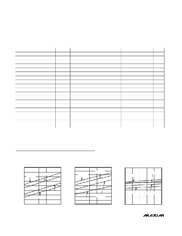
Typical Operating Characteristics
(T A = +25 ° C, unless otherwise noted.)
3.4
SUPPLY CURRENT vs. SUPPLY VOLTAGE
(INTERFACE IDLE, ALL OUTPUTS OFF,
R SET = 720 ? )
5.2
SUPPLY CURRENT vs. SUPPLY VOLTAGE
(INTERFACE IDLE, ALL OUTPUTS
OFF, R SET = 360 ? )
15
SUPPLY CURRENT vs. SUPPLY VOLTAGE
(INTERFACE IDLE, ALL OUTPUTS
ON, R SET = 720 ? )
3.3
3.2
T A = +125°C
T A = +85 ° C
5.1
5.0
4.9
T A = +125 ° C
T A = +85 ° C
12
T A = +125 ° C
T A = +85 ° C
3.1
3.0
4.8
4.7
9
2.9
2.8
2.7
T A = -40 ° C
T A = +25 ° C
4.6
4.5
4.4
4.3
T A = -40 ° C
T A = +25 ° C
6
3
T A = -40 ° C
T A = +25 ° C
2.6
4.2
0
3.0
3.5
4.0
4.5
5.0
5.5
3.0
3.5
4.0
4.5
5.0
5.5
3.0
3.5
4.0
4.5
5.0
5.5
SUPPLY VOLTAGE (V)
SUPPLY VOLTAGE (V)
SUPPLY VOLTAGE (V)
4
_______________________________________________________________________________________
发布紧急采购,3分钟左右您将得到回复。
相关PDF资料
MAX6970AUE+
IC LED DRIVER LINEAR 16-TSSOP
MAX6971AUG+T
IC LED DRIVER LINEAR 24-TSSOP
MAX6974ATL+
IC LED DRIVER LINEAR 40-TQFN
MAX6977AAE+
IC LED DRIVER LINEAR 16-SSOP
MAX6978AUE+
IC LED DVR CONST-CURR 16TSSOP
MAX6979AUG+
IC LED DRIVER LINEAR 24-TSSOP
MAX6983AUG+T
IC LED DRIVER LINEAR 24-TSSOP
MAX71020AEUI+
IC ENERGY METER 1PH 28TSSOP
相关代理商/技术参数
MAX6968AAE+T
功能描述:LED显示驱动器 8-Port 5.5V Constant Current LED Driver RoHS:否 制造商:Micrel 数位数量:5 片段数量: 安装风格:SMD/SMT 封装 / 箱体:PLCC-44 工作电源电压:4.75 V to 11 V 最大电源电流:10 mA 最大工作温度:+ 85 C 最小工作温度:- 40 C 封装:Tube
MAX6968AAE-T
功能描述:LED显示驱动器 8-Port 5.5V Constant Current LED Driver RoHS:否 制造商:Micrel 数位数量:5 片段数量: 安装风格:SMD/SMT 封装 / 箱体:PLCC-44 工作电源电压:4.75 V to 11 V 最大电源电流:10 mA 最大工作温度:+ 85 C 最小工作温度:- 40 C 封装:Tube
MAX6968AEE
制造商:Maxim Integrated Products 功能描述:8-PORT, 5.5V CONSTANT-CURRENT LED DRIVER - Rail/Tube
MAX6968AEE+
制造商:Maxim Integrated Products 功能描述:- Rail/Tube
MAX6968APE
功能描述:LED显示驱动器 8-Port 5.5V Constant Current LED Driver RoHS:否 制造商:Micrel 数位数量:5 片段数量: 安装风格:SMD/SMT 封装 / 箱体:PLCC-44 工作电源电压:4.75 V to 11 V 最大电源电流:10 mA 最大工作温度:+ 85 C 最小工作温度:- 40 C 封装:Tube
MAX6968APE+
功能描述:LED显示驱动器 8-Port 5.5V Constant Current LED Driver RoHS:否 制造商:Micrel 数位数量:5 片段数量: 安装风格:SMD/SMT 封装 / 箱体:PLCC-44 工作电源电压:4.75 V to 11 V 最大电源电流:10 mA 最大工作温度:+ 85 C 最小工作温度:- 40 C 封装:Tube
MAX6968AUE
功能描述:LED显示驱动器 8-Port 5.5V Constant Current LED Driver RoHS:否 制造商:Micrel 数位数量:5 片段数量: 安装风格:SMD/SMT 封装 / 箱体:PLCC-44 工作电源电压:4.75 V to 11 V 最大电源电流:10 mA 最大工作温度:+ 85 C 最小工作温度:- 40 C 封装:Tube
MAX6968AUE+
功能描述:LED显示驱动器 8-Port 5.5V Constant Current LED Driver RoHS:否 制造商:Micrel 数位数量:5 片段数量: 安装风格:SMD/SMT 封装 / 箱体:PLCC-44 工作电源电压:4.75 V to 11 V 最大电源电流:10 mA 最大工作温度:+ 85 C 最小工作温度:- 40 C 封装:Tube